Uncovering Gradual Shifts in Support Beams

Uncovering Gradual Shifts in Support Beams

Recognizing Shifts in the Home Foundation

Title: Uncovering Gradual Shifts in Support Beams: A Journey into Structural Integrity


Preventative maintenance can reduce the need for extensive foundation repairs foundation wall repair service construction.

In the world of construction and engineering, the integrity of support beams is crucial to the safety and longevity of any structure. Over time, these beams may undergo gradual shifts due to various factors, such as changes in load distribution, environmental conditions, or material fatigue. Uncovering these shifts is essential for maintaining the structural integrity of buildings and ensuring the safety of their occupants. In this essay, we will explore the importance of identifying gradual shifts in support beams and the methods used to detect them.


Support beams are the backbone of any structure, bearing the weight of the building and transferring loads to the foundation. As buildings age and endure the test of time, these beams may experience subtle changes in their position or alignment. These gradual shifts, while seemingly minor, can have significant consequences if left undetected and unaddressed. A shift in a support beam can lead to uneven load distribution, causing stress concentrations and potential failure points within the structure.


One of the primary reasons for gradual shifts in support beams is the natural settling of a building over time. As the soil beneath a structure compacts and adjusts, it can cause the foundation to shift, which in turn affects the support beams. Additionally, changes in the load distribution within a building, such as the addition or removal of heavy equipment or furniture, can also contribute to these shifts. Environmental factors, such as temperature fluctuations and moisture levels, can cause materials to expand and contract, further exacerbating the issue.


To uncover these gradual shifts, engineers and inspectors employ a variety of methods and technologies. One common approach is the use of laser scanning and 3D modeling to create a detailed digital representation of the structure. By comparing these models over time, professionals can identify even the slightest shifts in support beams and other structural elements. Another technique involves the installation of sensors and monitoring systems that continuously track the position and movement of beams, providing real-time data on any changes.


In addition to these high-tech methods, traditional inspection techniques, such as visual assessments and manual measurements, remain essential tools in uncovering gradual shifts. Experienced engineers and inspectors can often detect subtle changes in a structure's alignment or the presence of cracks and deformations that may indicate a shift in a support beam.


Once a gradual shift has been identified, it is crucial to assess its impact on the overall structural integrity of the building. In some cases, the shift may be minor and not pose an immediate threat. However, even small shifts should be monitored closely, as they can progress over time and lead to more significant issues. In situations where a shift is deemed critical, engineers may recommend reinforcement or repair measures to restore the beam's original alignment and load-bearing capacity.


The process of uncovering gradual shifts in support beams is an ongoing effort that requires vigilance and attention to detail. Regular inspections and monitoring are essential to detect these shifts early and take appropriate action. By staying proactive and utilizing a combination of advanced technologies and traditional techniques, engineers and building owners can ensure the long-term safety and stability of their structures.


In conclusion, uncovering gradual shifts in support beams is a vital aspect of maintaining structural integrity and ensuring the safety of buildings. These shifts, while often subtle, can have far-reaching consequences if left unaddressed. By employing a range of detection methods and staying proactive in their approach, professionals in the construction and engineering fields can identify and mitigate these shifts, preserving the longevity and safety of the structures they serve. As we continue to push the boundaries of architectural design and construction, the importance of uncovering gradual shifts in support beams will only grow, serving as a testament to our commitment to creating safe and resilient built environments.


Facebook about us:

Residential Foundation Repair Services

Strong Foundations, Strong Homes


Various examples of ornate ceilings

A ceiling /ˈslɪŋ/ is an overhead interior roof that covers the upper limits of a room. It is not generally considered a structural element, but a finished surface concealing the underside of the roof structure or the floor of a story above. Ceilings can be decorated to taste, and there are many examples of frescoes and artwork on ceilings, especially within religious buildings. A ceiling can also be the upper limit of a tunnel.

The most common type of ceiling is the dropped ceiling,[citation needed] which is suspended from structural elements above. Panels of drywall are fastened either directly to the ceiling joists or to a few layers of moisture-proof plywood which are then attached to the joists. Pipework or ducts can be run in the gap above the ceiling, and insulation and fireproofing material can be placed here. Alternatively, ceilings may be spray painted instead, leaving the pipework and ducts exposed but painted, and using spray foam.

A subset of the dropped ceiling is the suspended ceiling, wherein a network of aluminum struts, as opposed to drywall, are attached to the joists, forming a series of rectangular spaces. Individual pieces of cardboard are then placed inside the bottom of those spaces so that the outer side of the cardboard, interspersed with aluminum rails, is seen as the ceiling from below. This makes it relatively easy to repair the pipes and insulation behind the ceiling, since all that is necessary is to lift off the cardboard, rather than digging through the drywall and then replacing it.

Other types of ceiling include the cathedral ceiling, the concave or barrel-shaped ceiling, the stretched ceiling and the coffered ceiling. Coving often links the ceiling to the surrounding walls. Ceilings can play a part in reducing fire hazard, and a system is available for rating the fire resistance of dropped ceilings.

Types

[edit]
California tract home with an open-beam ceiling, 1960

Ceilings are classified according to their appearance or construction. A cathedral ceiling is any tall ceiling area similar to those in a church. A dropped ceiling is one in which the finished surface is constructed anywhere from a few inches or centimeters to several feet or a few meters below the structure above it. This may be done for aesthetic purposes, such as achieving a desirable ceiling height; or practical purposes such as acoustic damping or providing a space for HVAC or piping. An inverse of this would be a raised floor. A concave or barrel-shaped ceiling is curved or rounded upward, usually for visual or acoustical value, while a coffered ceiling is divided into a grid of recessed square or octagonal panels, also called a "lacunar ceiling". A cove ceiling uses a curved plaster transition between wall and ceiling; it is named for cove molding, a molding with a concave curve.[1] A stretched ceiling (or stretch ceiling) uses a number of individual panels using material such as PVC fixed to a perimeter rail.[2]

Elements

[edit]

Ceilings have frequently been decorated with fresco painting, mosaic tiles and other surface treatments. While hard to execute (at least in place) a decorated ceiling has the advantage that it is largely protected from damage by fingers and dust. In the past, however, this was more than compensated for by the damage from smoke from candles or a fireplace. Many historic buildings have celebrated ceilings. Perhaps the most famous is the Sistine Chapel ceiling by Michelangelo.

Ceiling height, particularly in the case of low ceilings, may have psychological impacts. [3]

Fire-resistance rated ceilings

[edit]

The most common ceiling that contributes to fire-resistance ratings in commercial and residential construction is the dropped ceiling. In the case of a dropped ceiling, the rating is achieved by the entire system, which is both the structure above, from which the ceilings is suspended, which could be a concrete floor or a timber floor, as well as the suspension mechanism and, finally the lowest membrane or dropped ceiling. Between the structure that the dropped ceiling is suspended from and the dropped membrane, such as a T-bar ceiling or a layer of drywall, there is often some room for mechanical and electrical piping, wiring and ducting to run.

An independent ceiling, however, can be constructed such that it has a stand-alone fire-resistance rating. Such systems must be tested without the benefit of being suspended from a slab above in order to prove that the resulting system is capable of holding itself up. This type of ceiling would be installed to protect items above from fire.

[edit]

See also

[edit]
  • Beam ceiling
  • Hammerbeam roof
  • Hollow-core slab
  • Moulding (decorative)
  • Popcorn ceiling
  • Scottish Renaissance painted ceilings
  • Tin ceiling
  • Passive fire protection
  • Fire test
  • Hy-Rib

References

[edit]
  1. ^ "Casa de las Ratas 2/2/2003". Archived from the original on September 29, 2008. Retrieved September 14, 2008.
  2. ^ Corky Binggeli (2011). Interior Graphic Standards: Student Edition. John Wiley & Sons. p. 220. ISBN 978-1-118-09935-3.
  3. ^ Meyers-Levy, Joan; Zhu, Rui (Juliet) (August 2007). "The Influence of Ceiling Height: The Effect of Priming on the Type of Processing That People Use". Journal of Consumer Research. 34 (2): 174–186. doi:10.1086/519146. JSTOR 10.1086/519146. S2CID 16607244.
  4. ^ Melvin, Jeremy (2006). …isme Să Înțelegem Stilurile Arhitecturale (in Romanian). Enciclopedia RAO. p. 39. ISBN 973-717-075-X.
  5. ^ Bresc-Bautier, Geneviève (2008). The Louvre, a Tale of a Palace. Musée du Louvre Éditions. p. 26. ISBN 978-2-7572-0177-0.
  6. ^ Bresc-Bautier, Geneviève (2008). The Louvre, a Tale of a Palace. Musée du Louvre Éditions. p. 30. ISBN 978-2-7572-0177-0.
  7. ^ Bresc-Bautier, Geneviève (2008). The Louvre, a Tale of a Palace. Musée du Louvre Éditions. p. 55. ISBN 978-2-7572-0177-0.
  8. ^ Bresc-Bautier, Geneviève (2008). The Louvre, a Tale of a Palace. Musée du Louvre Éditions. p. 106. ISBN 978-2-7572-0177-0.
  9. ^ Bresc-Bautier, Geneviève (2008). The Louvre, a Tale of a Palace. Musée du Louvre Éditions. p. 138. ISBN 978-2-7572-0177-0.
  10. ^ Marinache, Oana (2015). Ernest Donaud - visul liniei (in Romanian). Editura Istoria Artei. p. 79. ISBN 978-606-94042-8-7.
[edit]
  • Media related to Ceilings at Wikimedia Commons
  • "Ceiling" . Encyclopædia Britannica. Vol. 5 (11th ed.). 1911.
  • "Ceiling" . New International Encyclopedia. 1904.
  • Merriam-Webster ceiling definition


In geotechnical engineering, soil compaction is the process in which stress applied to a soil causes densification as air is displaced from the pores between the soil grains. When stress is applied that causes densification due to water (or other liquid) being displaced from between the soil grains, then consolidation, not compaction, has occurred. Normally, compaction is the result of heavy machinery compressing the soil, but it can also occur due to the passage of, for example, animal feet.

In soil science and agronomy, soil compaction is usually a combination of both engineering compaction and consolidation, so may occur due to a lack of water in the soil, the applied stress being internal suction due to water evaporation[1] as well as due to passage of animal feet. Affected soils become less able to absorb rainfall, thus increasing runoff and erosion. Plants have difficulty in compacted soil because the mineral grains are pressed together, leaving little space for air and water, which are essential for root growth. Burrowing animals also find it a hostile environment, because the denser soil is more difficult to penetrate. The ability of a soil to recover from this type of compaction depends on climate, mineralogy and fauna. Soils with high shrink–swell capacity, such as vertisols, recover quickly from compaction where moisture conditions are variable (dry spells shrink the soil, causing it to crack). But clays such as kaolinite, which do not crack as they dry, cannot recover from compaction on their own unless they host ground-dwelling animals such as earthworms—the Cecil soil series is an example.

Before soils can be compacted in the field, some laboratory tests are required to determine their engineering properties. Among various properties, the maximum dry density and the optimum moisture content are vital and specify the required density to be compacted in the field.[2]

A 10 tonne excavator is here equipped with a narrow sheepsfoot roller to compact the fill over newly placed sewer pipe, forming a stable support for a new road surface.
A compactor/roller fitted with a sheepsfoot drum, operated by U.S. Navy Seabees
Vibrating roller with plain drum as used for compacting asphalt and granular soils
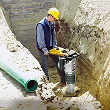
Vibratory rammer in action

In construction

[edit]

Soil compaction is a vital part of the construction process. It is used for support of structural entities such as building foundations, roadways, walkways, and earth retaining structures to name a few. For a given soil type certain properties may deem it more or less desirable to perform adequately for a particular circumstance. In general, the preselected soil should have adequate strength, be relatively incompressible so that future settlement is not significant, be stable against volume change as water content or other factors vary, be durable and safe against deterioration, and possess proper permeability.[3]

When an area is to be filled or backfilled the soil is placed in layers called lifts. The ability of the first fill layers to be properly compacted will depend on the condition of the natural material being covered. If unsuitable material is left in place and backfilled, it may compress over a long period under the weight of the earth fill, causing settlement cracks in the fill or in any structure supported by the fill.[4] In order to determine if the natural soil will support the first fill layers, an area can be proofrolled. Proofrolling consists of utilizing a piece of heavy construction equipment to roll across the fill site and watching for deflections to be revealed. These areas will be indicated by the development of rutting, pumping, or ground weaving.[5]

To ensure adequate soil compaction is achieved, project specifications will indicate the required soil density or degree of compaction that must be achieved. These specifications are generally recommended by a geotechnical engineer in a geotechnical engineering report.

The soil type—that is, grain-size distributions, shape of the soil grains, specific gravity of soil solids, and amount and type of clay minerals, present—has a great influence on the maximum dry unit weight and optimum moisture content.[6] It also has a great influence on how the materials should be compacted in given situations. Compaction is accomplished by use of heavy equipment. In sands and gravels, the equipment usually vibrates, to cause re-orientation of the soil particles into a denser configuration. In silts and clays, a sheepsfoot roller is frequently used, to create small zones of intense shearing, which drives air out of the soil.

Determination of adequate compaction is done by determining the in-situ density of the soil and comparing it to the maximum density determined by a laboratory test. The most commonly used laboratory test is called the Proctor compaction test and there are two different methods in obtaining the maximum density. They are the standard Proctor and modified Proctor tests; the modified Proctor is more commonly used. For small dams, the standard Proctor may still be the reference.[5]

While soil under structures and pavements needs to be compacted, it is important after construction to decompact areas to be landscaped so that vegetation can grow.

Compaction methods

[edit]

There are several means of achieving compaction of a material. Some are more appropriate for soil compaction than others, while some techniques are only suitable for particular soils or soils in particular conditions. Some are more suited to compaction of non-soil materials such as asphalt. Generally, those that can apply significant amounts of shear as well as compressive stress, are most effective.

The available techniques can be classified as:

  1. Static – a large stress is slowly applied to the soil and then released.
  2. Impact – the stress is applied by dropping a large mass onto the surface of the soil.
  3. Vibrating – a stress is applied repeatedly and rapidly via a mechanically driven plate or hammer. Often combined with rolling compaction (see below).
  4. Gyrating – a static stress is applied and maintained in one direction while the soil is a subjected to a gyratory motion about the axis of static loading. Limited to laboratory applications.
  5. Rolling – a heavy cylinder is rolled over the surface of the soil. Commonly used on sports pitches. Roller-compactors are often fitted with vibratory devices to enhance their effectiveness.
  6. Kneading – shear is applied by alternating movement in adjacent positions. An example, combined with rolling compaction, is the 'sheepsfoot' roller used in waste compaction at landfills.

The construction plant available to achieve compaction is extremely varied and is described elsewhere.

Test methods in laboratory

[edit]

Soil compactors are used to perform test methods which cover laboratory compaction methods used to determine the relationship between molding water content and dry unit weight of soils. Soil placed as engineering fill is compacted to a dense state to obtain satisfactory engineering properties such as, shear strength, compressibility, or permeability. In addition, foundation soils are often compacted to improve their engineering properties. Laboratory compaction tests provide the basis for determining the percent compaction and molding water content needed to achieve the required engineering properties, and for controlling construction to assure that the required compaction and water contents are achieved. Test methods such as EN 13286-2, EN 13286-47, ASTM D698, ASTM D1557, AASHTO T99, AASHTO T180, AASHTO T193, BS 1377:4 provide soil compaction testing procedures.[7]

See also

[edit]
  • Soil compaction (agriculture)
  • Soil degradation
  • Compactor
  • Earthwork
  • Soil structure
  • Aeration
  • Shear strength (soil)
Multiquip RX1575 Rammax Sheepsfoot Trench Compaction Roller on the jobsite in San Diego, California

References

[edit]
  1. ^ Soil compaction due to lack of water in soil
  2. ^ Jia, Xiaoyang; Hu, Wei; Polaczyk, Pawel; Gong, Hongren; Huang, Baoshan (2019). "Comparative Evaluation of Compacting Process for Base Materials using Lab Compaction Methods". Transportation Research Record: Journal of the Transportation Research Board. 2673 (4): 558–567. doi:10.1177/0361198119837953. ISSN 0361-1981.
  3. ^ McCarthy, David F. (2007). Essentials of Soil Mechanics and Foundations. Upper Saddle River, NJ: Pearson Prentice Hall. p. 595. ISBN 978-0-13-114560-3.
  4. ^ McCarthy, David F. (2007). Essentials of Soil Mechanics and Foundations. Upper Saddle River, NJ: Pearson Prentice Hall. pp. 601–602. ISBN 978-0-13-114560-3.
  5. ^ a b McCarthy, David F. (2007). Essentials of Soil Mechanics and Foundations. Upper Saddle River, NJ: Pearson Prentice Hall. p. 602. ISBN 978-0-13-114560-3.
  6. ^ Das, Braja M. (2002). Principles of Geotechnical Engineering. Pacific Grove, CA: Brooks/Cole. p. 105. ISBN 0-534-38742-X.
  7. ^ "Automatic Soil Compactor". cooper.co.uk. Cooper Research Technology. Archived from the original on 27 August 2014. Retrieved 8 September 2014.


Photo
Photo
Photo
Photo

Reviews for


Jeffery James

(5)

Very happy with my experience. They were prompt and followed through, and very helpful in fixing the crack in my foundation.

Sarah McNeily

(5)

USS was excellent. They are honest, straightforward, trustworthy, and conscientious. They thoughtfully removed the flowers and flower bulbs to dig where they needed in the yard, replanted said flowers and spread the extra dirt to fill in an area of the yard. We've had other services from different companies and our yard was really a mess after. They kept the job site meticulously clean. The crew was on time and friendly. I'd recommend them any day! Thanks to Jessie and crew.

Jim de Leon

(5)

It was a pleasure to work with Rick and his crew. From the beginning, Rick listened to my concerns and what I wished to accomplish. Out of the 6 contractors that quoted the project, Rick seemed the MOST willing to accommodate my wishes. His pricing was definitely more than fair as well. I had 10 push piers installed to stabilize and lift an addition of my house. The project commenced at the date that Rick had disclosed initially and it was completed within the same time period expected (based on Rick's original assessment). The crew was well informed, courteous, and hard working. They were not loud (even while equipment was being utilized) and were well spoken. My neighbors were very impressed on how polite they were when they entered / exited my property (saying hello or good morning each day when they crossed paths). You can tell they care about the customer concerns. They ensured that the property would be put back as clean as possible by placing MANY sheets of plywood down prior to excavating. They compacted the dirt back in the holes extremely well to avoid large stock piles of soils. All the while, the main office was calling me to discuss updates and expectations of completion. They provided waivers of lien, certificates of insurance, properly acquired permits, and JULIE locates. From a construction background, I can tell you that I did not see any flaws in the way they operated and this an extremely professional company. The pictures attached show the push piers added to the foundation (pictures 1, 2 & 3), the amount of excavation (picture 4), and the restoration after dirt was placed back in the pits and compacted (pictures 5, 6 & 7). Please notice that they also sealed two large cracks and steel plated these cracks from expanding further (which you can see under my sliding glass door). I, as well as my wife, are extremely happy that we chose United Structural Systems for our contractor. I would happily tell any of my friends and family to use this contractor should the opportunity arise!

Chris Abplanalp

(5)

USS did an amazing job on my underpinning on my house, they were also very courteous to the proximity of my property line next to my neighbor. They kept things in order with all the dirt/mud they had to excavate. They were done exactly in the timeframe they indicated, and the contract was very details oriented with drawings of what would be done. Only thing that would have been nice, is they left my concrete a little muddy with boot prints but again, all-in-all a great job

Dave Kari

(5)

What a fantastic experience! Owner Rick Thomas is a trustworthy professional. Nick and the crew are hard working, knowledgeable and experienced. I interviewed every company in the area, big and small. A homeowner never wants to hear that they have foundation issues. Out of every company, I trusted USS the most, and it paid off in the end. Highly recommend.

View GBP