Discovering Polyurethane Foam Applications

Discovering Polyurethane Foam Applications

Discovering Polyurethane Foam Applications


Advanced monitoring tools improve the accuracy of foundation repair assessments foundation repair expert service brickwork.

Polyurethane foam, an incredibly versatile material, has become a cornerstone in numerous industries, revolutionizing the way we think about comfort, insulation, and even safety. From the soft cushions we sink into after a long day to the robust insulation keeping our homes warm, the applications of polyurethane foam are vast and varied. As we delve into the world of this remarkable material, we uncover a tapestry of innovation and practicality that continues to evolve.


One of the most familiar applications of polyurethane foam is in furniture and bedding. The soft, plush feel of a high-quality sofa or the supportive embrace of a memory foam mattress is often the result of this material. What makes polyurethane foam particularly appealing in these contexts is its ability to conform to the body, providing personalized comfort and support. This adaptability not only enhances our daily lives but also caters to the needs of individuals requiring specialized support, such as those with back pain or other medical conditions.


Beyond the realm of comfort, polyurethane foam plays a crucial role in the construction industry. Its excellent insulating properties make it an ideal choice for maintaining energy efficiency in buildings. Whether it's sprayed into the walls of a new home or used in the form of rigid panels, polyurethane foam helps to keep the warmth in during winter and the heat out during summer. This not only contributes to a more comfortable living environment but also significantly reduces energy costs, making it a sustainable choice in our increasingly eco-conscious world.


The automotive industry has also embraced polyurethane foam, utilizing it in seat cushions, headrests, and even armrests. The material's durability and resistance to wear and tear make it perfect for the rigors of daily use. Moreover, its lightweight nature contributes to improved fuel efficiency, a critical factor in today's environmentally focused market. From luxury vehicles to family cars, polyurethane foam enhances the driving experience, providing comfort without compromising on performance.


In the realm of safety, polyurethane foam has found a unique niche. It is used in the manufacturing of life jackets and other flotation devices, where its buoyancy and water-resistant properties are invaluable. Additionally, the foam's ability to absorb impact makes it a key component in protective gear, ranging from sports equipment to industrial safety helmets. This application of polyurethane foam underscores its versatility and its capacity to save lives and prevent injuries.


The medical field has also benefited from the properties of polyurethane foam. In wound care, the material's breathability and absorbency make it an excellent choice for dressings that promote healing. It is also used in prosthetics, where its lightweight and durable nature provides comfort and functionality to patients. The adaptability of polyurethane foam to meet the specific needs of medical applications highlights its potential to improve the quality of life for countless individuals.


As we continue to explore the applications of polyurethane foam, we are constantly reminded of its potential to innovate and improve. From the comfort of our homes to the safety of our workplaces, this material touches nearly every aspect of our lives. Its ability to be molded into various shapes and densities, combined with its durability and versatility, ensures that polyurethane foam will remain a vital component in our ever-evolving world. As we look to the future, the discovery of new applications for this remarkable material will undoubtedly continue to surprise and delight us, pushing the boundaries of what we thought possible.


Facebook about us:

Residential Foundation Repair Services

Strong Foundations, Strong Homes


The Leaning Tower of Pisa – an example of a problem due to deformation of soil
Slope instability issues for a temporary flood control levee in North Dakota, 2009
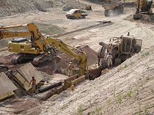
Earthwork in Germany
Fox Glacier, New Zealand: Soil produced and transported by intense weathering and erosion

Soil mechanics is a branch of soil physics and applied mechanics that describes the behavior of soils. It differs from fluid mechanics and solid mechanics in the sense that soils consist of a heterogeneous mixture of fluids (usually air and water) and particles (usually clay, silt, sand, and gravel) but soil may also contain organic solids and other matter.[1][2][3][4] Along with rock mechanics, soil mechanics provides the theoretical basis for analysis in geotechnical engineering,[5] a subdiscipline of civil engineering, and engineering geology, a subdiscipline of geology. Soil mechanics is used to analyze the deformations of and flow of fluids within natural and man-made structures that are supported on or made of soil, or structures that are buried in soils.[6] Example applications are building and bridge foundations, retaining walls, dams, and buried pipeline systems. Principles of soil mechanics are also used in related disciplines such as geophysical engineering, coastal engineering, agricultural engineering, and hydrology.

This article describes the genesis and composition of soil, the distinction between pore water pressure and inter-granular effective stress, capillary action of fluids in the soil pore spaces, soil classification, seepage and permeability, time dependent change of volume due to squeezing water out of tiny pore spaces, also known as consolidation, shear strength and stiffness of soils. The shear strength of soils is primarily derived from friction between the particles and interlocking, which are very sensitive to the effective stress.[7][6] The article concludes with some examples of applications of the principles of soil mechanics such as slope stability, lateral earth pressure on retaining walls, and bearing capacity of foundations.

Genesis and composition of soils

[edit]

Genesis

[edit]

The primary mechanism of soil creation is the weathering of rock. All rock types (igneous rock, metamorphic rock and sedimentary rock) may be broken down into small particles to create soil. Weathering mechanisms are physical weathering, chemical weathering, and biological weathering [1][2][3] Human activities such as excavation, blasting, and waste disposal, may also create soil. Over geologic time, deeply buried soils may be altered by pressure and temperature to become metamorphic or sedimentary rock, and if melted and solidified again, they would complete the geologic cycle by becoming igneous rock.[3]

Physical weathering includes temperature effects, freeze and thaw of water in cracks, rain, wind, impact and other mechanisms. Chemical weathering includes dissolution of matter composing a rock and precipitation in the form of another mineral. Clay minerals, for example can be formed by weathering of feldspar, which is the most common mineral present in igneous rock.

The most common mineral constituent of silt and sand is quartz, also called silica, which has the chemical name silicon dioxide. The reason that feldspar is most common in rocks but silica is more prevalent in soils is that feldspar is much more soluble than silica.

Silt, Sand, and Gravel are basically little pieces of broken rocks.

According to the Unified Soil Classification System, silt particle sizes are in the range of 0.002 mm to 0.075 mm and sand particles have sizes in the range of 0.075 mm to 4.75 mm.

Gravel particles are broken pieces of rock in the size range 4.75 mm to 100 mm. Particles larger than gravel are called cobbles and boulders.[1][2]

Transport

[edit]
Example soil horizons. a) top soil and colluvium b) mature residual soil c) young residual soil d) weathered rock

Soil deposits are affected by the mechanism of transport and deposition to their location. Soils that are not transported are called residual soils—they exist at the same location as the rock from which they were generated. Decomposed granite is a common example of a residual soil. The common mechanisms of transport are the actions of gravity, ice, water, and wind. Wind blown soils include dune sands and loess. Water carries particles of different size depending on the speed of the water, thus soils transported by water are graded according to their size. Silt and clay may settle out in a lake, and gravel and sand collect at the bottom of a river bed. Wind blown soil deposits (aeolian soils) also tend to be sorted according to their grain size. Erosion at the base of glaciers is powerful enough to pick up large rocks and boulders as well as soil; soils dropped by melting ice can be a well graded mixture of widely varying particle sizes. Gravity on its own may also carry particles down from the top of a mountain to make a pile of soil and boulders at the base; soil deposits transported by gravity are called colluvium.[1][2]

The mechanism of transport also has a major effect on the particle shape. For example, low velocity grinding in a river bed will produce rounded particles. Freshly fractured colluvium particles often have a very angular shape.

Soil composition

[edit]

Soil mineralogy

[edit]

Silts, sands and gravels are classified by their size, and hence they may consist of a variety of minerals. Owing to the stability of quartz compared to other rock minerals, quartz is the most common constituent of sand and silt. Mica, and feldspar are other common minerals present in sands and silts.[1] The mineral constituents of gravel may be more similar to that of the parent rock.

The common clay minerals are montmorillonite or smectite, illite, and kaolinite or kaolin. These minerals tend to form in sheet or plate like structures, with length typically ranging between 10−7 m and 4x10⁻⁶ m and thickness typically ranging between 10−9 m and 2x10⁻⁶ m, and they have a relatively large specific surface area. The specific surface area (SSA) is defined as the ratio of the surface area of particles to the mass of the particles. Clay minerals typically have specific surface areas in the range of 10 to 1,000 square meters per gram of solid.[3] Due to the large surface area available for chemical, electrostatic, and van der Waals interaction, the mechanical behavior of clay minerals is very sensitive to the amount of pore fluid available and the type and amount of dissolved ions in the pore fluid.[1]

The minerals of soils are predominantly formed by atoms of oxygen, silicon, hydrogen, and aluminum, organized in various crystalline forms. These elements along with calcium, sodium, potassium, magnesium, and carbon constitute over 99 per cent of the solid mass of soils.[1]

Grain size distribution

[edit]

Soils consist of a mixture of particles of different size, shape and mineralogy. Because the size of the particles obviously has a significant effect on the soil behavior, the grain size and grain size distribution are used to classify soils. The grain size distribution describes the relative proportions of particles of various sizes. The grain size is often visualized in a cumulative distribution graph which, for example, plots the percentage of particles finer than a given size as a function of size. The median grain size, , is the size for which 50% of the particle mass consists of finer particles. Soil behavior, especially the hydraulic conductivity, tends to be dominated by the smaller particles, hence, the term "effective size", denoted by , is defined as the size for which 10% of the particle mass consists of finer particles.

Sands and gravels that possess a wide range of particle sizes with a smooth distribution of particle sizes are called well graded soils. If the soil particles in a sample are predominantly in a relatively narrow range of sizes, the sample is uniformly graded. If a soil sample has distinct gaps in the gradation curve, e.g., a mixture of gravel and fine sand, with no coarse sand, the sample may be gap graded. Uniformly graded and gap graded soils are both considered to be poorly graded. There are many methods for measuring particle-size distribution. The two traditional methods are sieve analysis and hydrometer analysis.

Sieve analysis
[edit]
Sieve

The size distribution of gravel and sand particles are typically measured using sieve analysis. The formal procedure is described in ASTM D6913-04(2009).[8] A stack of sieves with accurately dimensioned holes between a mesh of wires is used to separate the particles into size bins. A known volume of dried soil, with clods broken down to individual particles, is put into the top of a stack of sieves arranged from coarse to fine. The stack of sieves is shaken for a standard period of time so that the particles are sorted into size bins. This method works reasonably well for particles in the sand and gravel size range. Fine particles tend to stick to each other, and hence the sieving process is not an effective method. If there are a lot of fines (silt and clay) present in the soil it may be necessary to run water through the sieves to wash the coarse particles and clods through.

A variety of sieve sizes are available. The boundary between sand and silt is arbitrary. According to the Unified Soil Classification System, a #4 sieve (4 openings per inch) having 4.75 mm opening size separates sand from gravel and a #200 sieve with an 0.075 mm opening separates sand from silt and clay. According to the British standard, 0.063 mm is the boundary between sand and silt, and 2 mm is the boundary between sand and gravel.[3]

Hydrometer analysis
[edit]

The classification of fine-grained soils, i.e., soils that are finer than sand, is determined primarily by their Atterberg limits, not by their grain size. If it is important to determine the grain size distribution of fine-grained soils, the hydrometer test may be performed. In the hydrometer tests, the soil particles are mixed with water and shaken to produce a dilute suspension in a glass cylinder, and then the cylinder is left to sit. A hydrometer is used to measure the density of the suspension as a function of time. Clay particles may take several hours to settle past the depth of measurement of the hydrometer. Sand particles may take less than a second. Stokes' law provides the theoretical basis to calculate the relationship between sedimentation velocity and particle size. ASTM provides the detailed procedures for performing the Hydrometer test.

Clay particles can be sufficiently small that they never settle because they are kept in suspension by Brownian motion, in which case they may be classified as colloids.

Mass-volume relations

[edit]
A phase diagram of soil indicating the masses and volumes of air, solid, water, and voids

There are a variety of parameters used to describe the relative proportions of air, water and solid in a soil. This section defines these parameters and some of their interrelationships.[2][6] The basic notation is as follows:

, , and represent the volumes of air, water and solids in a soil mixture;
, , and represent the weights of air, water and solids in a soil mixture;
, , and represent the masses of air, water and solids in a soil mixture;
, , and represent the densities of the constituents (air, water and solids) in a soil mixture;

Note that the weights, W, can be obtained by multiplying the mass, M, by the acceleration due to gravity, g; e.g.,

Specific Gravity is the ratio of the density of one material compared to the density of pure water ().

Specific gravity of solids,

Note that specific weight, conventionally denoted by the symbol may be obtained by multiplying the density ( ) of a material by the acceleration due to gravity, .

Density, bulk density, or wet density, , are different names for the density of the mixture, i.e., the total mass of air, water, solids divided by the total volume of air water and solids (the mass of air is assumed to be zero for practical purposes):

Dry density, , is the mass of solids divided by the total volume of air water and solids:

Buoyant density, , defined as the density of the mixture minus the density of water is useful if the soil is submerged under water:

where is the density of water

Water content, is the ratio of mass of water to mass of solid. It is easily measured by weighing a sample of the soil, drying it out in an oven and re-weighing. Standard procedures are described by ASTM.

Void ratio, , is the ratio of the volume of voids to the volume of solids:

Porosity, , is the ratio of volume of voids to the total volume, and is related to the void ratio:

Degree of saturation, , is the ratio of the volume of water to the volume of voids:

From the above definitions, some useful relationships can be derived by use of basic algebra.

Soil classification

[edit]

Geotechnical engineers classify the soil particle types by performing tests on disturbed (dried, passed through sieves, and remolded) samples of the soil. This provides information about the characteristics of the soil grains themselves. Classification of the types of grains present in a soil does not[clarification needed] account for important effects of the structure or fabric of the soil, terms that describe compactness of the particles and patterns in the arrangement of particles in a load carrying framework as well as the pore size and pore fluid distributions. Engineering geologists also classify soils based on their genesis and depositional history.

Classification of soil grains

[edit]

In the US and other countries, the Unified Soil Classification System (USCS) is often used for soil classification. Other classification systems include the British Standard BS 5930 and the AASHTO soil classification system.[3]

Classification of sands and gravels

[edit]

In the USCS, gravels (given the symbol G) and sands (given the symbol S) are classified according to their grain size distribution. For the USCS, gravels may be given the classification symbol GW (well-graded gravel), GP (poorly graded gravel), GM (gravel with a large amount of silt), or GC (gravel with a large amount of clay). Likewise sands may be classified as being SW, SP, SM or SC. Sands and gravels with a small but non-negligible amount of fines (5–12%) may be given a dual classification such as SW-SC.

Atterberg limits

[edit]

Clays and Silts, often called 'fine-grained soils', are classified according to their Atterberg limits; the most commonly used Atterberg limits are the liquid limit (denoted by LL or ), plastic limit (denoted by PL or ), and shrinkage limit (denoted by SL).

The liquid limit is the water content at which the soil behavior transitions from a plastic solid to a liquid. The plastic limit is the water content at which the soil behavior transitions from that of a plastic solid to a brittle solid. The Shrinkage Limit corresponds to a water content below which the soil will not shrink as it dries. The consistency of fine grained soil varies in proportional to the water content in a soil.

As the transitions from one state to another are gradual, the tests have adopted arbitrary definitions to determine the boundaries of the states. The liquid limit is determined by measuring the water content for which a groove closes after 25 blows in a standard test.[9][clarification needed] Alternatively, a fall cone test apparatus may be used to measure the liquid limit. The undrained shear strength of remolded soil at the liquid limit is approximately 2 kPa.[4][10] The plastic limit is the water content below which it is not possible to roll by hand the soil into 3 mm diameter cylinders. The soil cracks or breaks up as it is rolled down to this diameter. Remolded soil at the plastic limit is quite stiff, having an undrained shear strength of the order of about 200 kPa.[4][10]

The plasticity index of a particular soil specimen is defined as the difference between the liquid limit and the plastic limit of the specimen; it is an indicator of how much water the soil particles in the specimen can absorb, and correlates with many engineering properties like permeability, compressibility, shear strength and others. Generally, the clay having high plasticity have lower permeability and also they are also difficult to be compacted.

Classification of silts and clays

[edit]

According to the Unified Soil Classification System (USCS), silts and clays are classified by plotting the values of their plasticity index and liquid limit on a plasticity chart. The A-Line on the chart separates clays (given the USCS symbol C) from silts (given the symbol M). LL=50% separates high plasticity soils (given the modifier symbol H) from low plasticity soils (given the modifier symbol L). A soil that plots above the A-line and has LL>50% would, for example, be classified as CH. Other possible classifications of silts and clays are ML, CL and MH. If the Atterberg limits plot in the"hatched" region on the graph near the origin, the soils are given the dual classification 'CL-ML'.

[edit]

Liquidity index

[edit]

The effects of the water content on the strength of saturated remolded soils can be quantified by the use of the liquidity index, LI:

When the LI is 1, remolded soil is at the liquid limit and it has an undrained shear strength of about 2 kPa. When the soil is at the plastic limit, the LI is 0 and the undrained shear strength is about 200 kPa.[4][11]

Relative density

[edit]

The density of sands (cohesionless soils) is often characterized by the relative density,

where: is the "maximum void ratio" corresponding to a very loose state, is the "minimum void ratio" corresponding to a very dense state and is the in situ void ratio. Methods used to calculate relative density are defined in ASTM D4254-00(2006).[12]

Thus if the sand or gravel is very dense, and if the soil is extremely loose and unstable.

Seepage: steady state flow of water

[edit]
A cross section showing the water table varying with surface topography as well as a perched water table
In soil mechanics, seepage is the movement of water through soil. If fluid pressures in a soil deposit are uniformly increasing with depth according to , where is the depth below the water table, then hydrostatic conditions will prevail and the fluids will not be flowing through the soil. However, if the water table is sloping or there is a perched water table as indicated in the accompanying sketch, then seepage will occur. For steady state seepage, the seepage velocities are not varying with time. If the water tables are changing levels with time, or if the soil is in the process of consolidation, then steady state conditions do not apply.

Effective stress and capillarity: hydrostatic conditions

[edit]
Spheres immersed in water, reducing effective stress

To understand the mechanics of soils it is necessary to understand how normal stresses and shear stresses are shared by the different phases. Neither gas nor liquid provide significant resistance to shear stress. The shear resistance of soil is provided by friction and interlocking of the particles. The friction depends on the intergranular contact stresses between solid particles. The normal stresses, on the other hand, are shared by the fluid and the particles.[7] Although the pore air is relatively compressible, and hence takes little normal stress in most geotechnical problems, liquid water is relatively incompressible and if the voids are saturated with water, the pore water must be squeezed out in order to pack the particles closer together.

The principle of effective stress, introduced by Karl Terzaghi, states that the effective stress σ' (i.e., the average intergranular stress between solid particles) may be calculated by a simple subtraction of the pore pressure from the total stress:

[7]

where σ is the total stress and u is the pore pressure. It is not practical to measure σ' directly, so in practice the vertical effective stress is calculated from the pore pressure and vertical total stress. The distinction between the terms pressure and stress is also important. By definition, pressure at a point is equal in all directions but stresses at a point can be different in different directions. In soil mechanics, compressive stresses and pressures are considered to be positive and tensile stresses are considered to be negative, which is different from the solid mechanics sign convention for stress.

Total stress

[edit]

For level ground conditions, the total vertical stress at a point, , on average, is the weight of everything above that point per unit area. The vertical stress beneath a uniform surface layer with density , and thickness is for example:

where is the acceleration due to gravity, and is the unit weight of the overlying layer. If there are multiple layers of soil or water above the point of interest, the vertical stress may be calculated by summing the product of the unit weight and thickness of all of the overlying layers. Total stress increases with increasing depth in proportion to the density of the overlying soil.

It is not possible to calculate the horizontal total stress in this way. Lateral earth pressures are addressed elsewhere.

Pore water pressure

[edit]

Hydrostatic conditions

[edit]
Water is drawn into a small tube by surface tension. Water pressure, u, is negative above and positive below the free water surface.

If the soil pores are filled with water that is not flowing but is static, the pore water pressures will be hydrostatic. The water table is located at the depth where the water pressure is equal to the atmospheric pressure. For hydrostatic conditions, the water pressure increases linearly with depth below the water table:

where is the density of water, and is the depth below the water table.

Capillary action

[edit]

Due to surface tension, water will rise up in a small capillary tube above a free surface of water. Likewise, water will rise up above the water table into the small pore spaces around the soil particles. In fact the soil may be completely saturated for some distance above the water table. Above the height of capillary saturation, the soil may be wet but the water content will decrease with elevation. If the water in the capillary zone is not moving, the water pressure obeys the equation of hydrostatic equilibrium, , but note that , is negative above the water table. Hence, hydrostatic water pressures are negative above the water table. The thickness of the zone of capillary saturation depends on the pore size, but typically, the heights vary between a centimeter or so for coarse sand to tens of meters for a silt or clay.[3] In fact the pore space of soil is a uniform fractal e.g. a set of uniformly distributed D-dimensional fractals of average linear size L. For the clay soil it has been found that L=0.15 mm and D=2.7.[13]

The surface tension of water explains why the water does not drain out of a wet sand castle or a moist ball of clay. Negative water pressures make the water stick to the particles and pull the particles to each other, friction at the particle contacts make a sand castle stable. But as soon as a wet sand castle is submerged below a free water surface, the negative pressures are lost and the castle collapses. Considering the effective stress equation, if the water pressure is negative, the effective stress may be positive, even on a free surface (a surface where the total normal stress is zero). The negative pore pressure pulls the particles together and causes compressive particle to particle contact forces. Negative pore pressures in clayey soil can be much more powerful than those in sand. Negative pore pressures explain why clay soils shrink when they dry and swell as they are wetted. The swelling and shrinkage can cause major distress, especially to light structures and roads.[14]

Later sections of this article address the pore water pressures for seepage and consolidation problems.

Consolidation: transient flow of water

[edit]
Consolidation analogy. The piston is supported by water underneath and a spring. When a load is applied to the piston, water pressure increases to support the load. As the water slowly leaks through the small hole, the load is transferred from the water pressure to the spring force.

Consolidation is a process by which soils decrease in volume. It occurs when stress is applied to a soil that causes the soil particles to pack together more tightly, therefore reducing volume. When this occurs in a soil that is saturated with water, water will be squeezed out of the soil. The time required to squeeze the water out of a thick deposit of clayey soil layer might be years. For a layer of sand, the water may be squeezed out in a matter of seconds. A building foundation or construction of a new embankment will cause the soil below to consolidate and this will cause settlement which in turn may cause distress to the building or embankment. Karl Terzaghi developed the theory of one-dimensional consolidation which enables prediction of the amount of settlement and the time required for the settlement to occur.[15] Afterwards, Maurice Biot fully developed the three-dimensional soil consolidation theory, extending the one-dimensional model previously developed by Terzaghi to more general hypotheses and introducing the set of basic equations of Poroelasticity.[7] Soils are tested with an oedometer test to determine their compression index and coefficient of consolidation.

When stress is removed from a consolidated soil, the soil will rebound, drawing water back into the pores and regaining some of the volume it had lost in the consolidation process. If the stress is reapplied, the soil will re-consolidate again along a recompression curve, defined by the recompression index. Soil that has been consolidated to a large pressure and has been subsequently unloaded is considered to be overconsolidated. The maximum past vertical effective stress is termed the preconsolidation stress. A soil which is currently experiencing the maximum past vertical effective stress is said to be normally consolidated. The overconsolidation ratio, (OCR) is the ratio of the maximum past vertical effective stress to the current vertical effective stress. The OCR is significant for two reasons: firstly, because the compressibility of normally consolidated soil is significantly larger than that for overconsolidated soil, and secondly, the shear behavior and dilatancy of clayey soil are related to the OCR through critical state soil mechanics; highly overconsolidated clayey soils are dilatant, while normally consolidated soils tend to be contractive.[2][3][4]

Shear behavior: stiffness and strength

[edit]
Typical stress strain curve for a drained dilatant soil

The shear strength and stiffness of soil determines whether or not soil will be stable or how much it will deform. Knowledge of the strength is necessary to determine if a slope will be stable, if a building or bridge might settle too far into the ground, and the limiting pressures on a retaining wall. It is important to distinguish between failure of a soil element and the failure of a geotechnical structure (e.g., a building foundation, slope or retaining wall); some soil elements may reach their peak strength prior to failure of the structure. Different criteria can be used to define the "shear strength" and the "yield point" for a soil element from a stress–strain curve. One may define the peak shear strength as the peak of a stress–strain curve, or the shear strength at critical state as the value after large strains when the shear resistance levels off. If the stress–strain curve does not stabilize before the end of shear strength test, the "strength" is sometimes considered to be the shear resistance at 15–20% strain.[14] The shear strength of soil depends on many factors including the effective stress and the void ratio.

The shear stiffness is important, for example, for evaluation of the magnitude of deformations of foundations and slopes prior to failure and because it is related to the shear wave velocity. The slope of the initial, nearly linear, portion of a plot of shear stress as a function of shear strain is called the shear modulus

Friction, interlocking and dilation

[edit]
Angle of repose

Soil is an assemblage of particles that have little to no cementation while rock (such as sandstone) may consist of an assembly of particles that are strongly cemented together by chemical bonds. The shear strength of soil is primarily due to interparticle friction and therefore, the shear resistance on a plane is approximately proportional to the effective normal stress on that plane.[3] The angle of internal friction is thus closely related to the maximum stable slope angle, often called the angle of repose.

But in addition to friction, soil derives significant shear resistance from interlocking of grains. If the grains are densely packed, the grains tend to spread apart from each other as they are subject to shear strain. The expansion of the particle matrix due to shearing was called dilatancy by Osborne Reynolds.[11] If one considers the energy required to shear an assembly of particles there is energy input by the shear force, T, moving a distance, x and there is also energy input by the normal force, N, as the sample expands a distance, y.[11] Due to the extra energy required for the particles to dilate against the confining pressures, dilatant soils have a greater peak strength than contractive soils. Furthermore, as dilative soil grains dilate, they become looser (their void ratio increases), and their rate of dilation decreases until they reach a critical void ratio. Contractive soils become denser as they shear, and their rate of contraction decreases until they reach a critical void ratio.

A critical state line separates the dilatant and contractive states for soil.

The tendency for a soil to dilate or contract depends primarily on the confining pressure and the void ratio of the soil. The rate of dilation is high if the confining pressure is small and the void ratio is small. The rate of contraction is high if the confining pressure is large and the void ratio is large. As a first approximation, the regions of contraction and dilation are separated by the critical state line.

Failure criteria

[edit]

After a soil reaches the critical state, it is no longer contracting or dilating and the shear stress on the failure plane is determined by the effective normal stress on the failure plane and critical state friction angle :

The peak strength of the soil may be greater, however, due to the interlocking (dilatancy) contribution. This may be stated:

where . However, use of a friction angle greater than the critical state value for design requires care. The peak strength will not be mobilized everywhere at the same time in a practical problem such as a foundation, slope or retaining wall. The critical state friction angle is not nearly as variable as the peak friction angle and hence it can be relied upon with confidence.[3][4][11]

Not recognizing the significance of dilatancy, Coulomb proposed that the shear strength of soil may be expressed as a combination of adhesion and friction components:[11]

It is now known that the and parameters in the last equation are not fundamental soil properties.[3][6][11][16] In particular, and are different depending on the magnitude of effective stress.[6][16] According to Schofield (2006),[11] the longstanding use of in practice has led many engineers to wrongly believe that is a fundamental parameter. This assumption that and are constant can lead to overestimation of peak strengths.[3][16]

Structure, fabric, and chemistry

[edit]

In addition to the friction and interlocking (dilatancy) components of strength, the structure and fabric also play a significant role in the soil behavior. The structure and fabric include factors such as the spacing and arrangement of the solid particles or the amount and spatial distribution of pore water; in some cases cementitious material accumulates at particle-particle contacts. Mechanical behavior of soil is affected by the density of the particles and their structure or arrangement of the particles as well as the amount and spatial distribution of fluids present (e.g., water and air voids). Other factors include the electrical charge of the particles, chemistry of pore water, chemical bonds (i.e. cementation -particles connected through a solid substance such as recrystallized calcium carbonate) [1][16]

Drained and undrained shear

[edit]
Moist sand along the shoreline is originally densely packed by the draining water. Foot pressure on the sand causes it to dilate (see: Reynolds dilatancy), drawing water from the surface into the pores.

The presence of nearly incompressible fluids such as water in the pore spaces affects the ability for the pores to dilate or contract.

If the pores are saturated with water, water must be sucked into the dilating pore spaces to fill the expanding pores (this phenomenon is visible at the beach when apparently dry spots form around feet that press into the wet sand).[clarification needed]

Similarly, for contractive soil, water must be squeezed out of the pore spaces to allow contraction to take place.

Dilation of the voids causes negative water pressures that draw fluid into the pores, and contraction of the voids causes positive pore pressures to push the water out of the pores. If the rate of shearing is very large compared to the rate that water can be sucked into or squeezed out of the dilating or contracting pore spaces, then the shearing is called undrained shear, if the shearing is slow enough that the water pressures are negligible, the shearing is called drained shear. During undrained shear, the water pressure u changes depending on volume change tendencies. From the effective stress equation, the change in u directly effects the effective stress by the equation:

and the strength is very sensitive to the effective stress. It follows then that the undrained shear strength of a soil may be smaller or larger than the drained shear strength depending upon whether the soil is contractive or dilative.

Shear tests

[edit]

Strength parameters can be measured in the laboratory using direct shear test, triaxial shear test, simple shear test, fall cone test and (hand) shear vane test; there are numerous other devices and variations on these devices used in practice today. Tests conducted to characterize the strength and stiffness of the soils in the ground include the Cone penetration test and the Standard penetration test.

Other factors

[edit]

The stress–strain relationship of soils, and therefore the shearing strength, is affected by:[17]

  1. soil composition (basic soil material): mineralogy, grain size and grain size distribution, shape of particles, pore fluid type and content, ions on grain and in pore fluid.
  2. state (initial): Defined by the initial void ratio, effective normal stress and shear stress (stress history). State can be describd by terms such as: loose, dense, overconsolidated, normally consolidated, stiff, soft, contractive, dilative, etc.
  3. structure: Refers to the arrangement of particles within the soil mass; the manner in which the particles are packed or distributed. Features such as layers, joints, fissures, slickensides, voids, pockets, cementation, etc., are part of the structure. Structure of soils is described by terms such as: undisturbed, disturbed, remolded, compacted, cemented; flocculent, honey-combed, single-grained; flocculated, deflocculated; stratified, layered, laminated; isotropic and anisotropic.
  4. Loading conditions: Effective stress path - drained, undrained, and type of loading - magnitude, rate (static, dynamic), and time history (monotonic, cyclic).

Applications

[edit]

Lateral earth pressure

[edit]

Lateral earth stress theory is used to estimate the amount of stress soil can exert perpendicular to gravity. This is the stress exerted on retaining walls. A lateral earth stress coefficient, K, is defined as the ratio of lateral (horizontal) effective stress to vertical effective stress for cohesionless soils (K=σ'h/σ'v). There are three coefficients: at-rest, active, and passive. At-rest stress is the lateral stress in the ground before any disturbance takes place. The active stress state is reached when a wall moves away from the soil under the influence of lateral stress, and results from shear failure due to reduction of lateral stress. The passive stress state is reached when a wall is pushed into the soil far enough to cause shear failure within the mass due to increase of lateral stress. There are many theories for estimating lateral earth stress; some are empirically based, and some are analytically derived.

Bearing capacity

[edit]

The bearing capacity of soil is the average contact stress between a foundation and the soil which will cause shear failure in the soil. Allowable bearing stress is the bearing capacity divided by a factor of safety. Sometimes, on soft soil sites, large settlements may occur under loaded foundations without actual shear failure occurring; in such cases, the allowable bearing stress is determined with regard to the maximum allowable settlement. It is important during construction and design stage of a project to evaluate the subgrade strength. The California Bearing Ratio (CBR) test is commonly used to determine the suitability of a soil as a subgrade for design and construction. The field Plate Load Test is commonly used to predict the deformations and failure characteristics of the soil/subgrade and modulus of subgrade reaction (ks). The Modulus of subgrade reaction (ks) is used in foundation design, soil-structure interaction studies and design of highway pavements.[citation needed]

Slope stability

[edit]
Simple slope slip section

The field of slope stability encompasses the analysis of static and dynamic stability of slopes of earth and rock-fill dams, slopes of other types of embankments, excavated slopes, and natural slopes in soil and soft rock.[18]

As seen to the right, earthen slopes can develop a cut-spherical weakness zone. The probability of this happening can be calculated in advance using a simple 2-D circular analysis package.[19] A primary difficulty with analysis is locating the most-probable slip plane for any given situation.[20] Many landslides have been analyzed only after the fact. Landslides vs. Rock strength are two factors for consideration.

Recent developments

[edit]

A recent finding in soil mechanics is that soil deformation can be described as the behavior of a dynamical system. This approach to soil mechanics is referred to as Dynamical Systems based Soil Mechanics (DSSM). DSSM holds simply that soil deformation is a Poisson process in which particles move to their final position at random shear strains.

The basis of DSSM is that soils (including sands) can be sheared till they reach a steady-state condition at which, under conditions of constant strain-rate, there is no change in shear stress, effective confining stress, and void ratio. The steady-state was formally defined[21] by Steve J. Poulos Archived 2020-10-17 at the Wayback Machine an associate professor at the Soil Mechanics Department of Harvard University, who built off a hypothesis that Arthur Casagrande was formulating towards the end of his career. The steady state condition is not the same as the "critical state" condition. It differs from the critical state in that it specifies a statistically constant structure at the steady state. The steady-state values are also very slightly dependent on the strain-rate.

Many systems in nature reach steady states, and dynamical systems theory describes such systems. Soil shear can also be described as a dynamical system.[22][23] The physical basis of the soil shear dynamical system is a Poisson process in which particles move to the steady-state at random shear strains.[24] Joseph[25] generalized this—particles move to their final position (not just steady-state) at random shear-strains. Because of its origins in the steady state concept, DSSM is sometimes informally called "Harvard soil mechanics."

DSSM provides for very close fits to stress–strain curves, including for sands. Because it tracks conditions on the failure plane, it also provides close fits for the post failure region of sensitive clays and silts something that other theories are not able to do. Additionally DSSM explains key relationships in soil mechanics that to date have simply been taken for granted, for example, why normalized undrained peak shear strengths vary with the log of the overconsolidation ratio and why stress–strain curves normalize with the initial effective confining stress; and why in one-dimensional consolidation the void ratio must vary with the log of the effective vertical stress, why the end-of-primary curve is unique for static load increments, and why the ratio of the creep value Cα to the compression index Cc must be approximately constant for a wide range of soils.[26]

See also

[edit]
  • Critical state soil mechanics
  • Earthquake engineering
  • Engineering geology
  • Geotechnical centrifuge modeling
  • Geotechnical engineering
  • Geotechnical engineering (Offshore)
  • Geotechnics
  • Hydrogeology, aquifer characteristics closely related to soil characteristics
  • International Society for Soil Mechanics and Geotechnical Engineering
  • Rock mechanics
  • Slope stability analysis

References

[edit]
  1. ^ a b c d e f g h Mitchell, J.K., and Soga, K. (2005) Fundamentals of soil behavior, Third edition, John Wiley and Sons, Inc., ISBN 978-0-471-46302-3
  2. ^ a b c d e f Santamarina, J.C., Klein, K.A., & Fam, M.A. (2001). Soils and Waves: Particulate Materials Behavior, Characterization and Process Monitoring. Wiley. ISBN 978-0-471-49058-6.cite book: CS1 maint: multiple names: authors list (link).
  3. ^ a b c d e f g h i j k l Powrie, W., Spon Press, 2004, Soil Mechanics – 2nd ed ISBN 0-415-31156-X
  4. ^ a b c d e f A Guide to Soil Mechanics, Bolton, Malcolm, Macmillan Press, 1979. ISBN 0-333-18931-0
  5. ^ "Built Environment – Routledge". Routledge.com. Retrieved 2017-01-14.
  6. ^ a b c d e Lambe, T. William & Robert V. Whitman. Soil Mechanics. Wiley, 1991; p. 29. ISBN 978-0-471-51192-2
  7. ^ a b c d Guerriero V., Mazzoli S. (2021). "Theory of Effective Stress in Soil and Rock and Implications for Fracturing Processes: A Review". Geosciences. 11 (3): 119. Bibcode:2021Geosc..11..119G. doi:10.3390/geosciences11030119.
  8. ^ ASTM Standard Test Methods of Particle-Size Distribution (Gradation) of Soils using Sieve Analysis. http://www.astm.org/Standards/D6913.htm Archived 2011-08-10 at the Wayback Machine
  9. ^ "Classification of Soils for Engineering Purposes: Annual Book of ASTM Standards". D 2487-83. 04 (8). American Society for Testing and Materials. 1985: 395–408. Archived from the original on 2010-09-14. Retrieved 2010-08-31. cite journal: Cite journal requires |journal= (help)
  10. ^ a b Wood, David Muir, Soil Behavior and Critical State Soil Mechanics, Cambridge University Press, 1990, ISBN 0-521-33249-4
  11. ^ a b c d e f g Disturbed soil properties and geotechnical design, Schofield, Andrew N., Thomas Telford, 2006. ISBN 0-7277-2982-9
  12. ^ ASTM Standard Test Methods for Minimum Index Density and Unit Weight of Soils and Calculation of Relative Density. http://www.astm.org/Standards/D4254.htm Archived 2011-09-07 at the Wayback Machine
  13. ^ Ozhovan, M.I.; Dmitriev, I.E.; Batyukhnova, O.G. (1993). "Fractal structure of pores in clay soil". Atomic Energy. 74 (3): 241–243. doi:10.1007/BF00739059. S2CID 95352427.
  14. ^ a b Holtz, R.D, and Kovacs, W.D., 1981. An Introduction to Geotechnical Engineering. Prentice-Hall, Inc. page 448
  15. ^ Terzaghi, K., 1943, Theoretical Soil Mechanics, John Wiley and Sons, New York
  16. ^ a b c d Terzaghi, K., Peck, R.B., Mesri, G. (1996) Soil mechanics in Engineering Practice, Third Edition, John Wiley & Sons, Inc.,ISBN 0-471-08658-4
  17. ^ Poulos, S. J. 1989. Advance Dam Engineering for Design, Construction, and Rehabilitation: Liquefaction Related Phenomena. Ed. Jansen, R.B, Van Nostrand Reinhold, pages 292–297.
  18. ^ Slope Stability (PDF). Engineer Manual. Vol. EM 1110-2-1902. United States Army Corps of Engineers. 3 Oct 2003. Archived (PDF) from the original on 2016-12-29. Retrieved 2017-01-18.
  19. ^ "Slope Stability Calculator". Retrieved 2006-12-14.
  20. ^ Chugh, A.K. (2002). "A method for locating critical slip surfaces in slope stability analysis: Discussion". Canadian Geotechnical Journal. 39 (3): 765–770. doi:10.1139/t02-042.
  21. ^ Poulos, Steve J. (1981). "The Steady State of Deformation". Journal of Geotechnical Engineering. 107 (GT5): 553–562.
  22. ^ Joseph, Paul G. (2009). "Constitutive Model of Soil Based on a Dynamical Systems Approach". Journal of Geotechnical and Geoenvironmental Engineering. 135 (8): 1155–1158. doi:10.1061/(asce)gt.1943-5606.0000001.
  23. ^ Joseph, Paul G. (2010). "A Dynamical Systems Based Approach to Soil Shear". Géotechnique. LX (10): 807–812. Bibcode:2010Getq...60..807J. doi:10.1680/geot.9.p.001.
  24. ^ Joseph, Paul G. (2012). "Physical Basis and Validation of a Constitutive Model for Soil Shear Derived from Micro-Structural Changes". International Journal of Geomechanics. 13 (4): 365–383. doi:10.1061/(asce)gm.1943-5622.0000209.
  25. ^ Joseph, Paul G. (2014). "Generalised dynamical systems soil deformation model". Geotechnical Research. 1 (1): 32–42. Bibcode:2014GeotR...1...32J. doi:10.1680/geores.14.00004.
  26. ^ Joseph, Paul G. (2017). Dynamical Systems-Based Soil Mechanics (first ed.). CRC Press/Balkema. p. 138. ISBN 9781138723221. Archived from the original on 2018-03-24. Retrieved 2017-05-14.
[edit]
  • Media related to Soil mechanics at Wikimedia Commons


Basement waterproofing involves techniques and materials used to prevent water from penetrating the basement of a house or a building. Waterproofing a basement that is below ground level can require the application of sealant materials, the installation of drains and sump pumps, and more.

Purpose

[edit]

Waterproofing is usually required by building codes for structures that are built at or below ground level. Waterproofing and drainage considerations are especially important in cases where ground water is likely to build up in the soil or where there is a high water table.

Water in the soil causes hydrostatic pressure to be exerted underneath basement floors and walls. This hydrostatic pressure can force water in through cracks, which can cause major structural damage as well as mold, decay, and other moisture-related problems.

Methods

[edit]

Several measures exist to prevent water from penetrating a basement foundation or to divert water that has penetrated a foundation:

  • French Drain
    French drain
    Interior wall and floor sealers
  • Interior water drainage
  • Exterior drainage
  • Exterior waterproofing coatings
  • Box type waterproofing[1]
  • Foundation crack injections
  • French drains
  • Sump pump

Interior sealants

[edit]

In poured concrete foundations, cracks and pipe penetrations are the most common entry points for seepage. These openings can be sealed from the interior. Epoxies, which are strong adhesives, or urethanes can be pressure injected into the openings, thus penetrating the foundation through to the exterior and cutting off the path of the seepage.

In masonry foundations, interior sealers will not provide permanent protection from water infiltration where hydrostatic pressure is present. However, interior sealers are good for preventing high atmospheric humidity inside the basement from absorbing into the porous masonry and causing spalling. Spalling is a condition where constant high humidity or moisture breaks down masonry surfaces, causing deterioration and shedding of the concrete surfaces.

Other coatings can be effective where condensation is the main source of wetness. It is also effective if the problem has minor dampness. Usually, interior waterproofing will not stop major leaks.

Interior water drainage

[edit]

Although interior water drainage is not technically waterproofing, it is a widely accepted technique in mitigating basement water and is generally referred to as a basement waterproofing solution. Many interior drainage systems are patented and recognized by Building Officials and Code Administrators(BOCA) as being effective in controlling basement water.

A common system for draining water that has penetrated a basement involves creating a channel around the perimeter of the basement alongside the foundation footers. A French drain, PVC pipe, or other drainage system is installed in the newly made channel. The installed drain is covered with new cement.

The drainage system collects any water entering the basement and drains it to an internally placed sump pump system, which will then pump the water out of the basement. The Federal Emergency Management Agency (FEMA) recommends basement waterproofing with a water alarm and "battery-operated backup pump" as a preventive measure against the high cost of flooding.[2] Wall conduits (such as dimple boards or other membranes) are fastened to the foundation wall and extend over the new drainage to guide any moisture down into the system.

Exterior waterproofing

[edit]

Waterproofing a structure from the exterior is the only method the U.S. International Building Code (IBC) recognizes as adequate to prevent structural damage caused by water intrusion.

Waterproofing an existing basement begins with excavating to the bottom sides of the footings. Once excavated, the walls are then power washed and allowed to dry. The dry walls are sealed with a waterproofing membrane,[3] and new drainage tiles (weeping tiles) are placed at the side of the footing.

A French drain, PVC pipe, or other drainage system is installed and water is led further from the basement.

Polymer

[edit]

Over the past ten years, polymer-based waterproofing products have been developed. Polymer-based products last for the lifetime of the building and are not affected by soil pH. Polymer-based waterproofing materials can be sprayed directly onto a wall, are very fast curing, and are semi-flexible, allowing for some movement of the substrate.

Causes of water seepage and leaks

[edit]

Water seepage in basement and crawl spaces usually occurs over long periods of time and can be caused by numerous factors.

  • Concrete is one of the most commonly used materials in home construction. When pockets of air are not removed during construction, or the mixture is not allowed to cure properly, the concrete can crack, which allows water to force its way through the wall.
  • Foundations (footings) are horizontal pads that define the perimeter of foundation walls. When footings are too narrow or are not laid deep enough, they are susceptible to movement caused by soil erosion.
  • Gutters and downspouts are used to catch rain water as it falls and to discharge it away from houses and buildings. When gutters are clogged or downspouts are broken, rainwater is absorbed by the soil near the foundation, increasing hydrostatic pressure.
  • Weeping tile is a porous plastic drain pipe installed around the perimeter of the house. The main purpose of external weeping tile is preventing water from getting into a basement. However, these pipes can become clogged or damaged, which causes excess water to put pressure on internal walls and basement floors.
  • Water build up inside window wells, after heavy rain or snow, can lead to leaks through basement window seams. Window well covers can be used to prevent water from accumulating in the window well.
  • Ground saturation is another common form of basement leaks. When the footing drain fails the ground around the basement can contain too much water and when the saturation point is met flooding can occur.

Warning signs of water damage

[edit]

Signs that water is seeping into a basement or crawlspace often take years to develop and may not be easily visible. Over time, multiple signs of damage may become evident and could lead to structural failure.

  • Cracked walls: Cracks may be horizontal, vertical, diagonal or stair-stepped. Severe pressure or structural damage is evident by widening cracks.
  • Buckling walls: Usually caused by hydrostatic pressure. Walls appear to be bowed inward.
  • Peeling paint: Water seeping through walls may lead to bubbling or peeling paint along basement walls.[4]
  • Efflorescence: White, powdery residue found on basement walls near the floor.
  • Mold: Fungi that usually grow in damp, dark areas and can cause respiratory problems after prolonged exposure.

Foundation crack injections

[edit]

Foundation crack injections are used when poured concrete foundations crack, either from settlement or the expansion and contraction of the concrete. Epoxy crack injections are typically used for structural purposes while hydrophobic or hydrophilic polyurethane injections are used to seal cracks to prevent penetration of moisture or water. Concrete is both strong and inexpensive, making it an ideal product in construction. However, concrete is not waterproof.

References

[edit]
  1. ^ Waheed, M. A. (11 July 2014). "Top tips to optimally use conventional waterproofing techniques". Business Standard India. Archived from the original on 5 July 2022. Retrieved 28 May 2021.
  2. ^ "FloodSmart | How to Prepare for a Flood and Minimize Losses". Archived from the original on 9 May 2020. Retrieved 20 March 2020.
  3. ^ Carter, Tim. "How to redirect water around a damp garage". The Washington Post. Archived from the original on 15 August 2016. Retrieved 2 November 2015.
  4. ^ Chodorov, Jill. "Basement flooding may put a damper on your home sale". The Washington Post. Archived from the original on 18 May 2018. Retrieved 2 November 2015.
Photo
Photo
Photo
Photo

Reviews for


Jeffery James

(5)

Very happy with my experience. They were prompt and followed through, and very helpful in fixing the crack in my foundation.

Sarah McNeily

(5)

USS was excellent. They are honest, straightforward, trustworthy, and conscientious. They thoughtfully removed the flowers and flower bulbs to dig where they needed in the yard, replanted said flowers and spread the extra dirt to fill in an area of the yard. We've had other services from different companies and our yard was really a mess after. They kept the job site meticulously clean. The crew was on time and friendly. I'd recommend them any day! Thanks to Jessie and crew.

Jim de Leon

(5)

It was a pleasure to work with Rick and his crew. From the beginning, Rick listened to my concerns and what I wished to accomplish. Out of the 6 contractors that quoted the project, Rick seemed the MOST willing to accommodate my wishes. His pricing was definitely more than fair as well. I had 10 push piers installed to stabilize and lift an addition of my house. The project commenced at the date that Rick had disclosed initially and it was completed within the same time period expected (based on Rick's original assessment). The crew was well informed, courteous, and hard working. They were not loud (even while equipment was being utilized) and were well spoken. My neighbors were very impressed on how polite they were when they entered / exited my property (saying hello or good morning each day when they crossed paths). You can tell they care about the customer concerns. They ensured that the property would be put back as clean as possible by placing MANY sheets of plywood down prior to excavating. They compacted the dirt back in the holes extremely well to avoid large stock piles of soils. All the while, the main office was calling me to discuss updates and expectations of completion. They provided waivers of lien, certificates of insurance, properly acquired permits, and JULIE locates. From a construction background, I can tell you that I did not see any flaws in the way they operated and this an extremely professional company. The pictures attached show the push piers added to the foundation (pictures 1, 2 & 3), the amount of excavation (picture 4), and the restoration after dirt was placed back in the pits and compacted (pictures 5, 6 & 7). Please notice that they also sealed two large cracks and steel plated these cracks from expanding further (which you can see under my sliding glass door). I, as well as my wife, are extremely happy that we chose United Structural Systems for our contractor. I would happily tell any of my friends and family to use this contractor should the opportunity arise!

Chris Abplanalp

(5)

USS did an amazing job on my underpinning on my house, they were also very courteous to the proximity of my property line next to my neighbor. They kept things in order with all the dirt/mud they had to excavate. They were done exactly in the timeframe they indicated, and the contract was very details oriented with drawings of what would be done. Only thing that would have been nice, is they left my concrete a little muddy with boot prints but again, all-in-all a great job

Dave Kari

(5)

What a fantastic experience! Owner Rick Thomas is a trustworthy professional. Nick and the crew are hard working, knowledgeable and experienced. I interviewed every company in the area, big and small. A homeowner never wants to hear that they have foundation issues. Out of every company, I trusted USS the most, and it paid off in the end. Highly recommend.

View GBP